
DPD02
NFC-Configurable 3-Phase voltage and frequency monitoring relay
Instruction manual

|

|

|

|

|

|

|

|
DANGER! Live parts. Heart attack, burns and other injuries. Disconnect the power supply and load before installing the device. The device should only be installed by qualified / authorized personnel. |

|
These instructions are an integral part of the product. They should be consulted for all situations tied to installation and use. They should be kept within easy reach of operators, in a clean place and in good conditions. |
Responsibility for disposal

|
The product must be disposed of at the relevant recycling centres specified by the government or local public authorities. Correct disposal and recycling will contribute to the prevention of potentially harmful consequences to the environment and persons. |
Service and warranty
In the event of malfunction, fault or for information on the warranty, contact the CARLO GAVAZZI branch or distributor in your country.
Packaging material
The packing material should be kept for redelivery in case of replacement or repair.
General warnings
|
UL NOTES
|
|
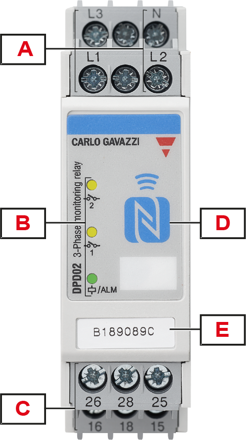
Element |
Description |
|---|---|
|
A |
Input terminals: connection of the line voltages (neutral when present) |
|
B |
Information LEDs:
|
|
C |
Output terminals: 2 x SPDT relay outputs |
|
D |
NFC interface: allows communication between DPD02 and smartphone, tablet or PC |
|
E |
Serial number: useful during the configuration if there is more than one product nearby |
Connect the 3-phase power supply and the neutral (if present) taking care of the sequence. Connect the relay output according to the ratings.
Automatic screwdriver can be used with maximum tightening torque 0.5 Nm.

|
|
Keep power OFF while connecting! |
(*) NOTE: fuses F of 315 mA delayed, if required by local law.
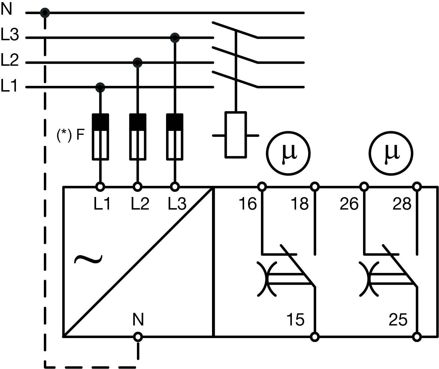
Terminals
| Power supply | L1, L2, L3, N |
| Relay 1 output | 15, 16, 18 |
|
Relay 2 output |
25, 26, 28 |
Each terminal can accept up to 2 x 2.5 mm2 wires.
Factory device configuration
DPD02 is factory configured with the parameters as listed in column related to your model.
|
Page |
Element |
DPD02DM44 |
|---|---|---|
|
Mains type |
Line type |
Delta |
|
Rated line voltage |
400 V AC |
|
|
Power ON delay |
0 s |
|
|
Setpoints |
Alarm 1 |
Over voltage |
|
Voltage value |
440 V AC |
|
|
Hysteresis |
2% |
|
|
Delay ON |
0 s |
|
|
Delay OFF |
0 s |
|
|
Alarm 2 |
Under voltage |
|
|
Voltage value |
360 V AC |
|
|
Hysteresis |
2% |
|
|
Delay ON |
0 s |
|
|
Delay OFF |
0 s |
|
| Priority alarms |
Phase loss enable |
ON |
|
Phase loss threshold |
85% |
|
|
Neutral loss |
Not active |
|
|
Phase sequence enable |
ON |
|
|
Out of range measurement |
ON |
|
| Output 1 |
Assignment |
Alarm 1 |
|
Logic |
Normally energized |
|
|
Logic operators |
None |
|
| Output 2 |
Assignment |
Alarm 2 |
|
Logic |
Normally energized |
|
|
Logic operators |
None |
|
Page |
Element |
DPD02DM44B |
|---|---|---|
|
Mains type |
Line type |
Delta |
|
Rated line voltage |
240 V AC |
|
|
Power ON delay |
0 s |
|
|
Setpoints |
Alarm 1 |
Over voltage |
|
Voltage value |
264 V AC |
|
|
Hysteresis |
2% |
|
|
Delay ON |
0 s |
|
|
Delay OFF |
0 s |
|
|
Alarm 2 |
Under voltage |
|
|
Voltage value |
216 V AC |
|
|
Hysteresis |
2% |
|
|
Delay ON |
0 s |
|
|
Delay OFF |
0 s |
|
| Priority alarms |
Phase loss enable |
ON |
|
Phase loss threshold |
85% |
|
|
Neutral loss |
Not active |
|
|
Phase sequence enable |
ON |
|
|
Out of range measurement |
ON |
|
| Output 1 |
Assignment |
Alarm 1 |
|
Logic |
Normally energized |
|
|
Logic operators |
None |
|
| Output 2 |
Assignment |
Alarm 2 |
|
Logic |
Normally energized |
|
|
Logic operators |
None |
Device configuration
DPD02 is equipped with built in NFC communication. It is possible to change the device configuration by means of smartphone (both Android and iOS) or tablet (Android only), equipped with NFC Transmission, or a Windows PC through a specific USB NFC reader/writer: ACR1252U.
Please refer to user manual for configuration software.
Windows Desktop App user manual http://cga.pub/?55eb09
Mobile App User Manual http://cga.pub/?73e8f2
Android App https://play.google.com/store/apps/details?id=us.belka.dpd&hl
iOS App https://apps.apple.com/it/app/dpd-manager/id1550610272
Windows Desktop App http://gavazziautomation.com/images/PIM/OTHERSTUFF/Setup_DPD.exe
|
Voltage measurement |
|
|---|---|
|
Typology |
3PH (Delta) or 3PH+N (Star) line voltage measurement on L1, L2, L3 and N lines |
|
Nominal range for line 3PH (Delta) |
177 to 552 V (delta voltage 208 V-15% to 480 V+15%) |
|
Nominal range for line 3PH+N (Star) |
102 to 318 V (star voltage 120 V-15% to 277 V+15%) |
| Adjustable setpoint range | 3PH (Delta) 177 to 552 V AC, 3PH+N (Star) 102 to 318 V AC |
| Resolution | 1 V |
| Accuracy | 1% reading +1 V |
|
Frequency measurement |
|
|---|---|
|
Typology |
3PH (Delta) or 3PH+N (Star) line frequency measurement on L1, L2, L3 and N lines |
|
Adjustable setpoint range |
45 to 440 Hz |
|
Resolution |
0.1 Hz |
|
Accuracy |
1% reading |
|
Asymmetry measurement |
|
|---|---|
|
Typology |
3PH (Delta) or 3PH+N (Star) line asymmetry measurement on L1, L2, L3 and N lines |
|
Adjustable setpoint range |
0 to 30% |
|
Resolution |
Compatible with direct measurements |
|
Accuracy |
|
Turn the power ON. If everything is OK the “ALM” LED will be green lit. LED 1 and LED 2 (with default configuration) will be both yellow lit.
In case of alarm the LED “ALM” will flash RED. The number of flashes shows the type of alarm triggered.
Active alarms can also be displayed on the PC or smartphone through the DPD App.
As soon as, or after alarm OFF delay elapsing, the fault cause is eliminated the normal operation will be restored, no need to RESET.
|
LEDs |
Status |
Description |
|---|---|---|
|
Green ( |
Green ON (steady) |
Power supply ON |
|
Green flashing (2 Hz) |
Alarm triggered but configured delay is elapsing |
|
|
Red, 1 flash |
Phase or neutral loss or incorrect phase sequence alarm |
|
|
Red, 2 flashes |
Under / over voltage alarm |
|
|
Red, 3 flashes |
Under / over frequency alarm |
|
|
Red, 4 flashes |
Asymmetry alarm |
|
| Red, 5 flashes | Measure out of range alarm | |
|
OFF |
Power supply OFF |
|
|
Yellow |
ON |
Relay output energised |
|
OFF |
Relay output de-energised |
|
|
Yellow |
ON |
Relay output energised |
|
OFF |
Relay output de-energised |
 )
) )
)NOTE: power supply ( _LED.png) )and "ALM" alarm in the same LED.
)and "ALM" alarm in the same LED.
There are 2 types of alarm:
|
Priority alarms |
|
|---|---|
|
Description |
Priority alarms trip both outputs at the same time when they are triggered. |
|
Type |
Phase loss Neutral loss (in "Star" configured systems) Incorrect phase sequence Out of range measurement |
|
Configuration |
Each one of the priority alarm can be disabled individually. The setpoint can be adjusted for the phase or neutral loss. |
|
Non priority alarms |
|
|---|---|
|
Description |
Non priority alarms are totally configurable by the user. Type of measurement to be monitored and trigger value can be freely set, within the specified ranges, and changed at any time. |
|
Type |
Undervoltage U< Overvoltage U> Overfrequency f> Underfrequency f< Asymmetry |
|
Configuration |
Up to 10 alarms among the above types can be configured. As there are 2 outputs on DPD02, some alarms can be configured without being directly associated to an output. Logical functions like AND and OR can be used to connect several alarms to the same relay output. |
|
Phase loss priority alarm |
|
|---|---|
|
Input variables |
L1-L2, L2-L3 and L3-L1 |
|
Adjustable setpoint |
60 to 90% (3-P systems) |
|
Reaction time |
≤ 200 ms |
|
Hysteresis |
2% fixed |
|
Delay ON |
0 s |
|
Delay OFF |
|
|
Neutral loss priority alarm |
|
|---|---|
|
Input variables |
L1-N, L2-N and L3-N |
|
Adjustable setpoint |
10 to 30% of VLN |
|
Reaction time |
≤ 200 ms |
|
Hysteresis |
2% fixed |
|
Delay ON |
0 s |
|
Delay OFF |
|
|
Phase sequence priority alarm |
|
|---|---|
|
Input variables |
Connection L1, L2, L3 |
|
Range |
No setting necessary |
|
Reaction time |
≤ 200 ms |
|
Hysteresis |
None |
|
Delay ON |
None |
|
Delay OFF |
None |
|
Measure out of range priority alarm |
|
|---|---|
|
Input variables |
Measure voltage, frequency, asymmetry |
|
Range |
No setting necessary |
|
Reaction time |
≤ 200 ms |
|
Hysteresis |
None |
|
Delay ON |
None |
|
Delay OFF |
None |
|
Over / under voltage non priority alarms |
|
|---|---|
|
Input variables |
Overvoltage, undervoltage |
|
Adjustable setpoint |
Free voltage level within the device range |
|
Reaction time |
≤ 200 ms |
|
Hysteresis |
1 to 5% |
|
Delay ON |
0 (< 200 ms) to 60 s |
|
Delay OFF |
0 (< 200 ms) to 600 s |
|
Over / under frequency non priority alarms |
|
|---|---|
|
Input variables |
Overfrequency, underfrequency |
|
Adjustable setpoint |
Free frequency level within the device range |
|
Reaction time |
≤ 200 ms |
|
Hysteresis |
0.1 to 5% |
|
Delay ON |
0 (< 200 ms) to 60 s |
|
Delay OFF |
0 (< 200 ms) to 600 s |
|
Voltage asymmetry non priority alarm |
|
|---|---|
|
Input variables |
Voltage asymmetry |
|
Adjustable setpoint |
1 to 30% (3-P systems) |
|
Reaction time |
≤ 200 ms |
|
Hysteresis |
2 to 5% |
|
Delay ON |
0 (< 200 ms) to 60 s |
|
Delay OFF |
0 (< 200 ms) to 600 s |
Operating diagram

Over / under voltage and over / under frequency monitoring (2 x SPDT relays)

Asymmetry monitoring

Total phase loss, phase sequence
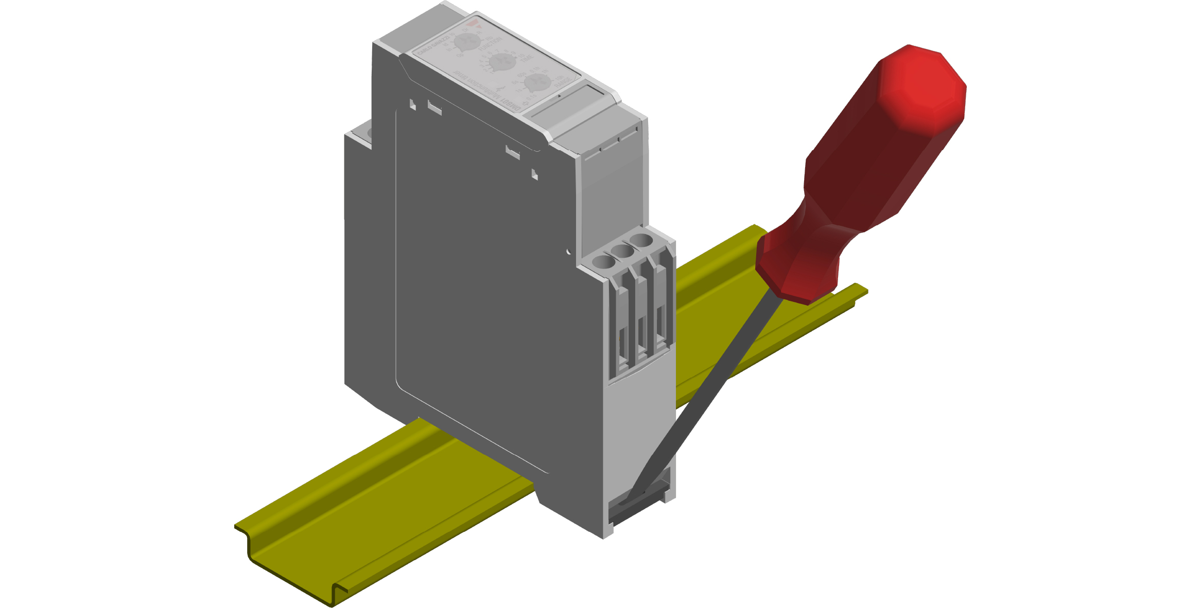
DIN-rail
Hang the device to the DIN-rail being sure that the spring closes. Use a screwdriver to remove the product as shown in figure.
 ,
,  ,
,  ,
,  ,
,