
DAA01, PAA01, DAA51, DAA71, DBA52, DMB01, PMB01, DMB51, DMB71
Electronic timers
Instruction manual

|

|

|

|

|

|

|

|
DANGER! Live parts. Heart attack, burns and other injuries. Disconnect the power supply and load before installing the device. The device should only be installed by qualified / authorized personnel. |

|
These instructions are an integral part of the product. They should be consulted for all situations tied to installation and use. They should be kept within easy reach of operators, in a clean place and in good conditions. |
Responsibility for disposal

|
The product must be disposed of at the relevant recycling centres specified by the government or local public authorities. Correct disposal and recycling will contribute to the prevention of potentially harmful consequences to the environment and persons. |
Service and warranty
In the event of malfunction, fault or for information on the warranty, contact the CARLO GAVAZZI branch or distributor in your country.
Packaging material
The packing material should be kept for redelivery in case of replacement or repair.
General warnings
|
UL NOTES
|
UL NOTES
|
|
|
|
|
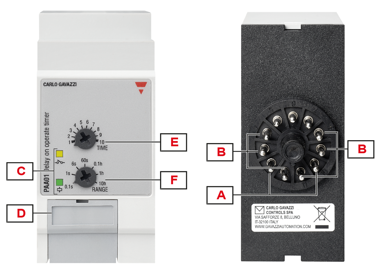
DAA01 |
PAA01 |

|
Element |
Description |
|---|---|
|
A |
Power supply |
|
B |
Output terminals:
|
|
C |
Information LEDs:
|
|
D |
Dip switch: setting the operating mode of the second relay |
|
E |
Time dial (TIME): time setting on relative scale |
|
F |
Range dial (RANGE): setting of time range |
|
|
|
|
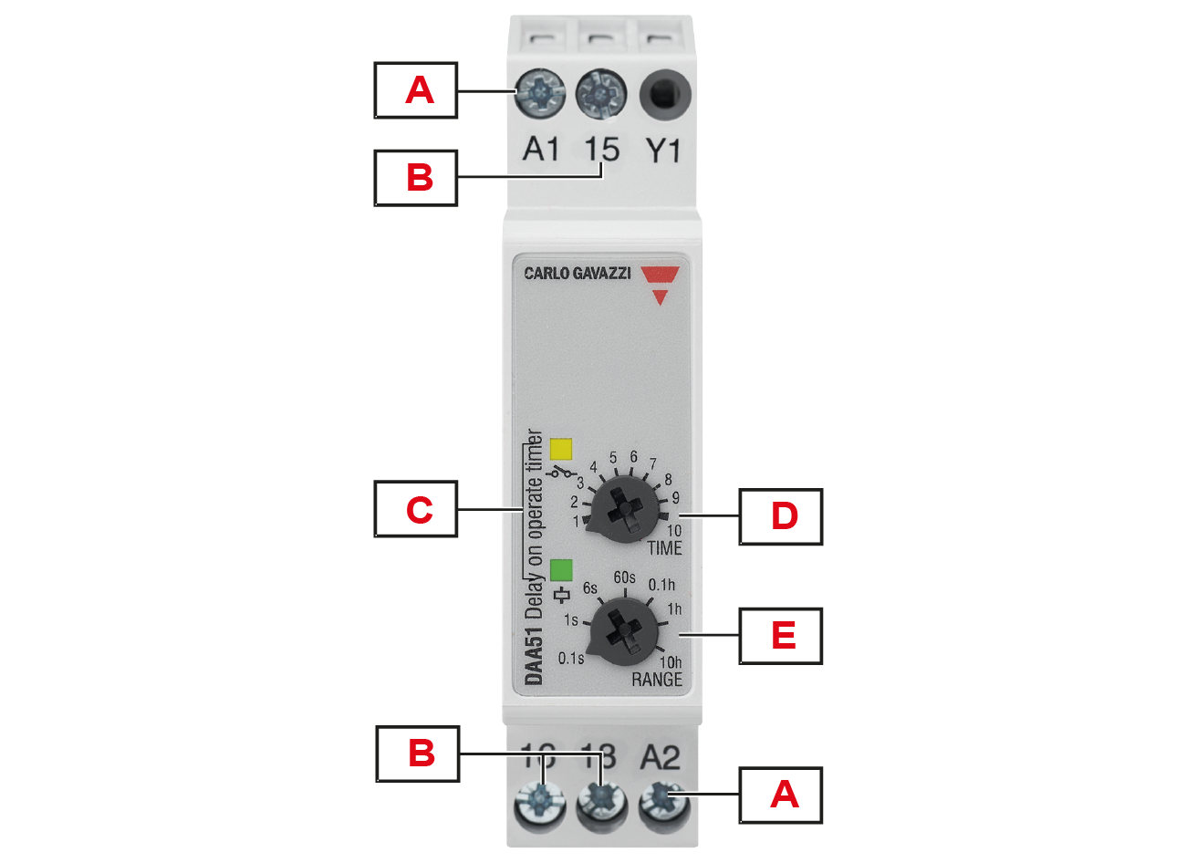
DAA51 |
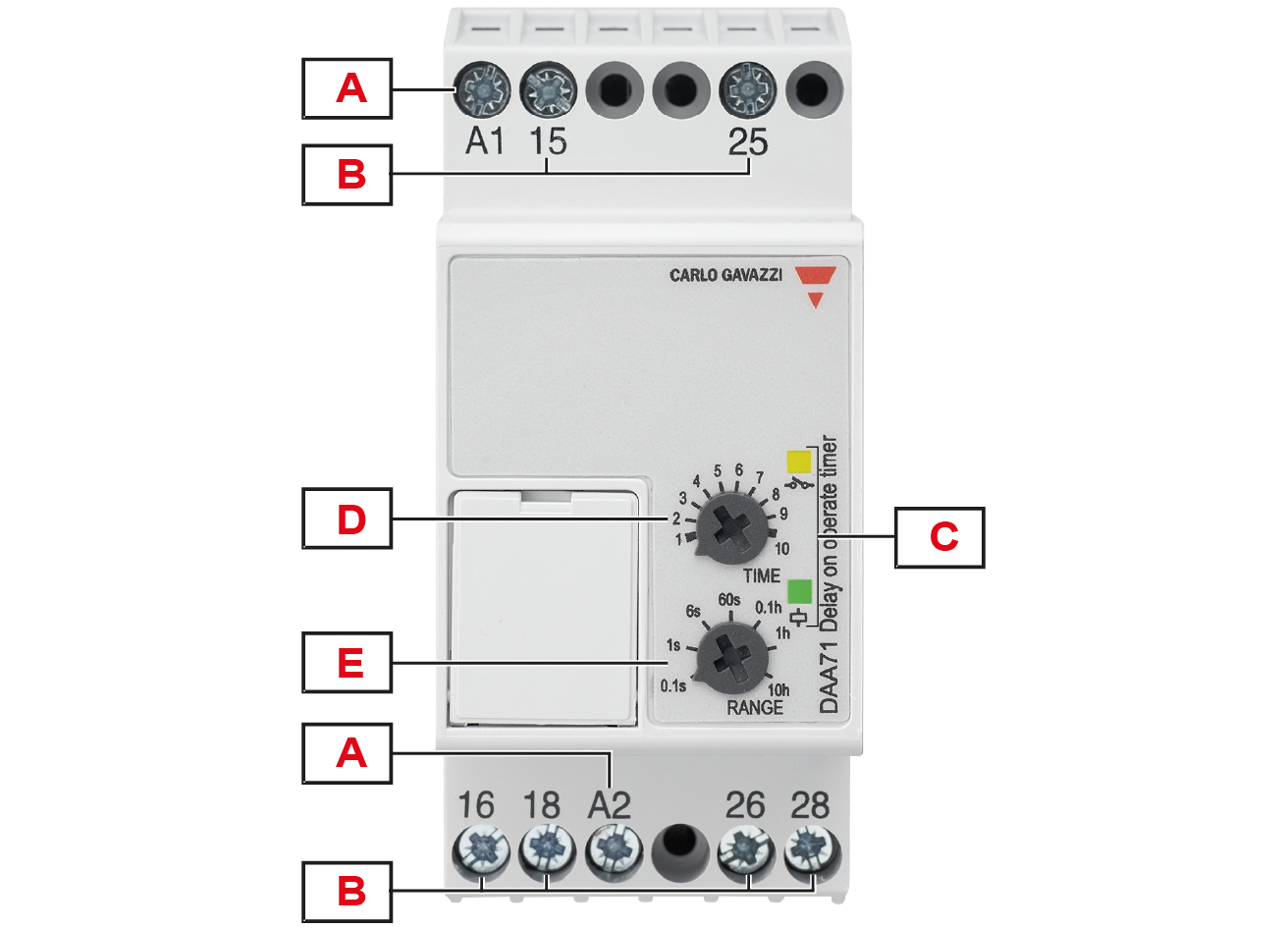
DAA71 |
|
Element |
Description |
|---|---|
|
A |
Power supply |
|
B |
Output terminals:
|
|
C |
Information LEDs:
|
|
D |
Time dial (TIME): time setting on relative scale |
|
E |
Range dial (RANGE): setting of time range |
|
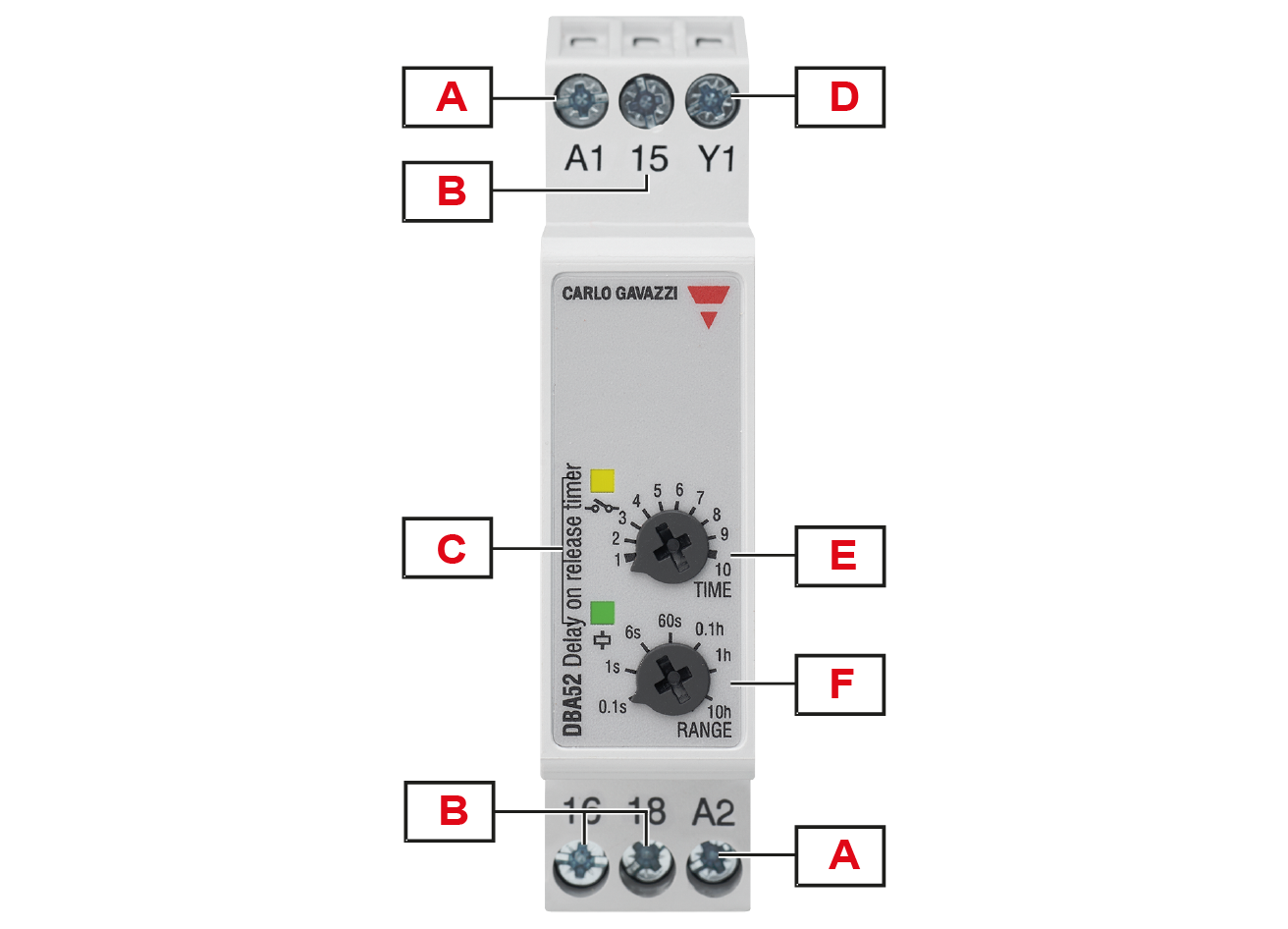
Element |
Description |
|---|---|
|
A |
Power supply |
|
B |
Output terminals:
|
|
C |
Information LEDs:
|
|
D |
Trigger input |
|
E |
Time dial (TIME): time setting on relative scale |
|
F |
Range dial (RANGE): setting of time range |
|
|
|
|
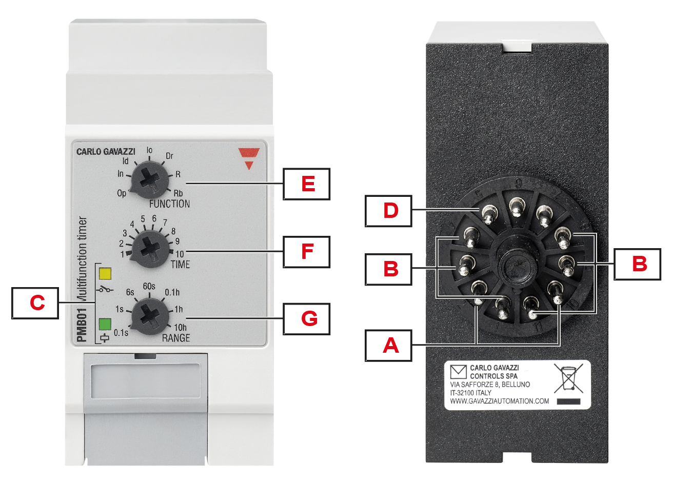
DMB01 |
PMB01 |
|
Element |
Description |
|---|---|
|
A |
Power supply |
|
B |
Output terminals:
|
|
C |
Information LEDs:
|
|
D |
Trigger input |
|
E |
Functions dial (FUNCTION): 7 selectable functions |
|
F |
Time dial (TIME): time setting on relative scale |
|
G |
Range dial (RANGE): setting of time range |
|
|
|
|
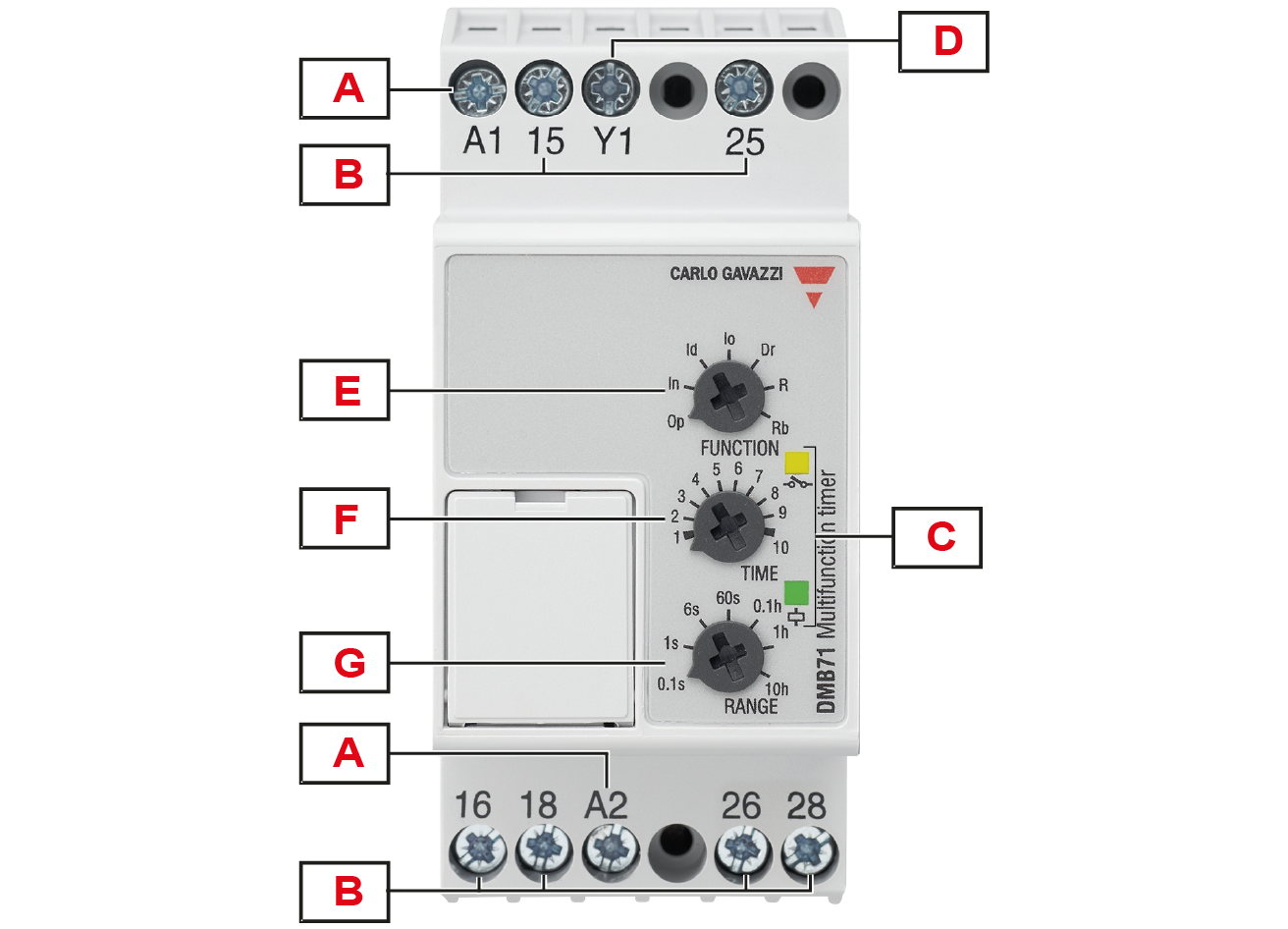
DMB51 |
DMB71 |
|
Element |
Description |
|---|---|
|
A |
Power supply |
|
B |
Output terminals:
|
|
C |
Information LEDs:
|
|
D |
Trigger input |
|
E |
Functions dial (FUNCTION): 7 selectable functions |
|
F |
Time dial (TIME): time setting on relative scale |
|
G |
Range dial (RANGE): setting of time range |
Connect the power supply.
Connect the relay output according to the ratings.
For DIN-rail versions automatic screwdriver can be used with maximum tightening torque:
DAA01: 0.5 Nm

DAA51 - DAA71: 0.8 Nm

|
|
Keep power OFF while connecting! |
DAA01C, DAA51
DAA01D, DAA71
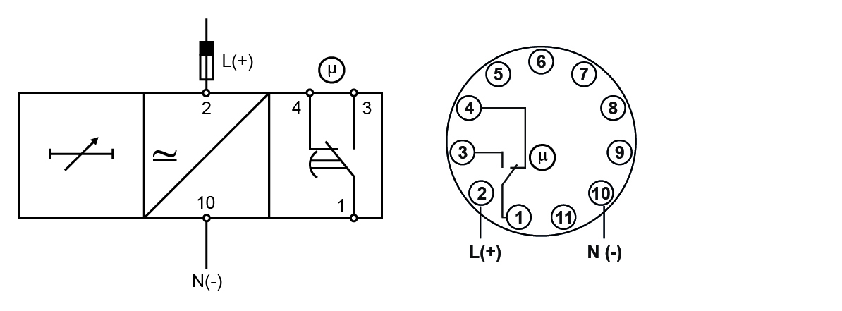
PAA01C
PPA01D
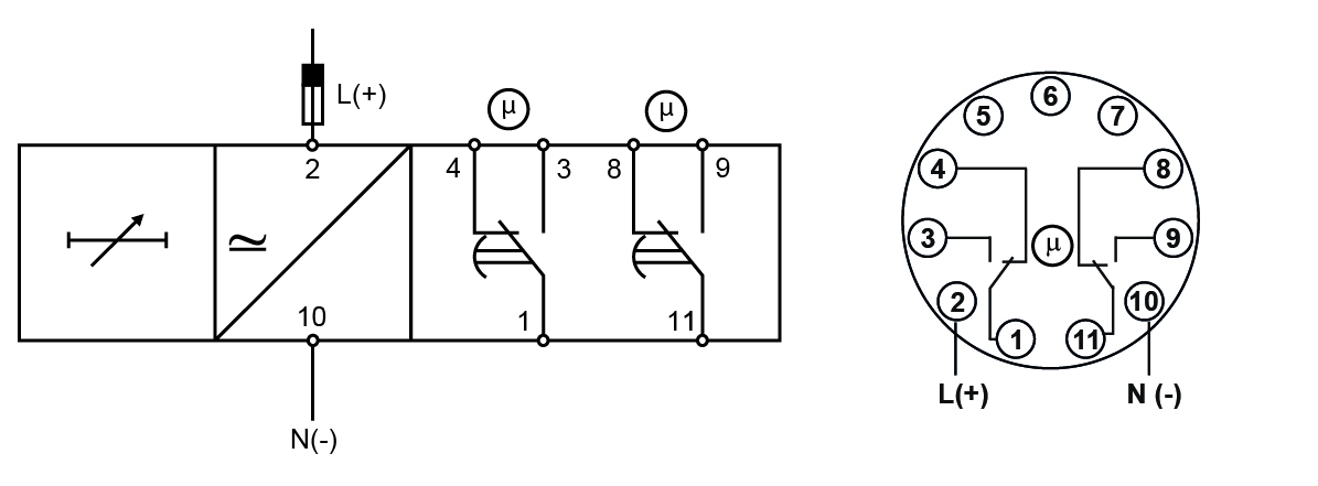
Terminals
| Power supply | DAA | A1, A2 |
| PAA | 2, 10 | |
| Relay output | DAA | 15, 16, 18 |
| PAA | 1, 3, 4 | |
|
2nd relay output |
DAA01D, DAA71 |
25, 26, 28 |
|
PAA01D |
8, 9, 11 |
|
|
Each terminal can accept up to 2.5 mm2 wires for DAA51 and DAA71, and 2 x 2.5 mm2 wires for DAA01. |
||
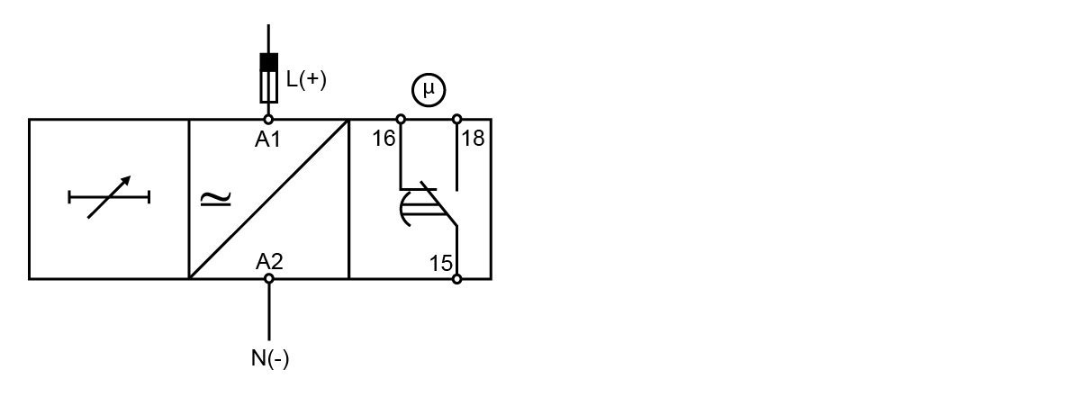
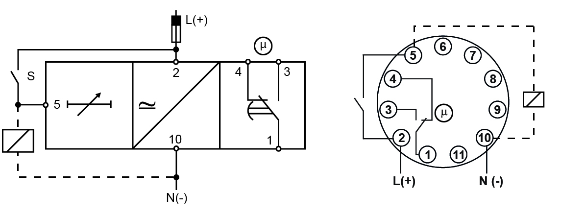
Connect the power supply.
Connect the trigger input S.
Connect the relay output according to the ratings.
It's possible to wire an additional load (i.e. a relay) between pins Y1 and A2, or 5 and 10, driven by the trigger contact without damaging the device.
For DIN-rail versions automatic screwdriver can be used with maximum tightening torque:
DMB01: 0.5 Nm
DBA52 - DMB51 - DMB71: 0.8 Nm
|
|
Keep power OFF while connecting! |
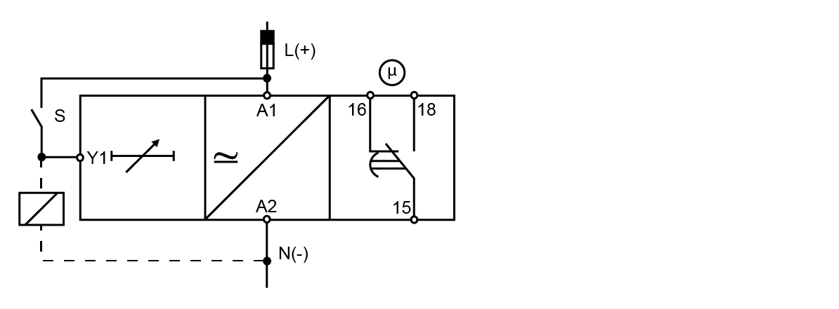
DBA52, DMB01C, DMB51
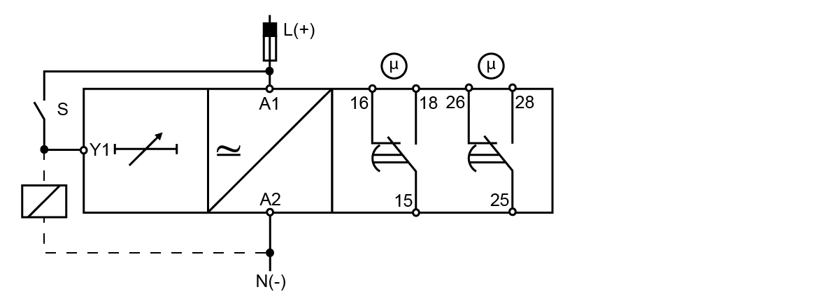
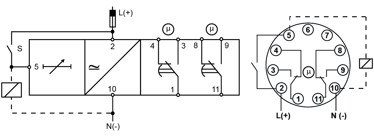
DMB01D, DMB71
PMB01C
PMB01D
Terminals
| Power supply | DBA, DMB | A1, A2 |
| PMB | 2, 10 | |
|
Trigger input |
DBA, DMB |
A1, Y1 |
|
PMB |
2, 5 |
|
| Relay output | DBA, DMB | 15, 16, 18 |
| PMB | 1, 3, 4 | |
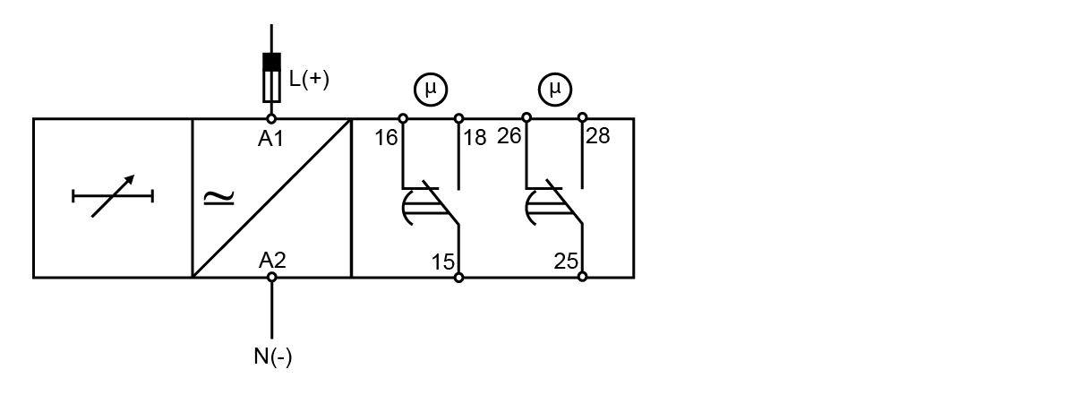
|
2nd relay output |
DMB01D |
25, 26, 28 |
|
PMB01D |
8, 9, 11 |
|
|
Additional load |
DBA, DMB |
Y1, A2 |
|
PMB |
5, 10 |
|
|
Each terminal can accept up to 2.5 mm2 wires for DBA52, DMB51 and DMB71 and 2 x 2.5 mm2 wires for DMB01. |
||
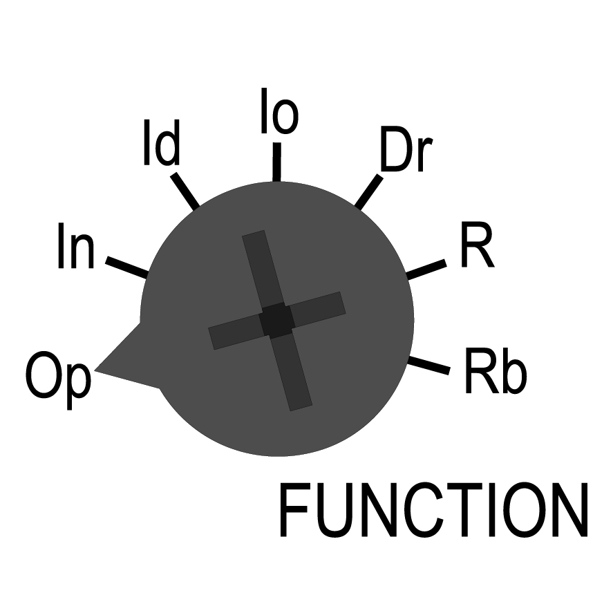
Select the desired function by the FUNCTION dial (only for DMB01, DMB51, DMB71 and PMB01):
| Function | |
|---|---|
|
|
Op - delay on operate In - interval Io - interval on trigger open Id - double interval Dr - delay on release R - symmetrical recycler (ON first) Rb - symmetrical recycler (OFF first) |
Adjust the time period on relative scale: from 1 to 10 with respect to the chosen range, setting the TIME dial.
| Delay time | |
|---|---|
|
|
Multiplier with respect to the chosen range set by the RANGE dial. |
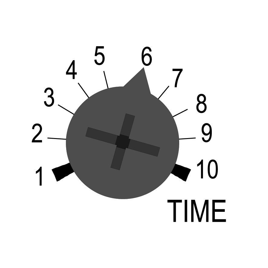
Select the desired time range by the RANGE dial.
| Ranges | |
|---|---|
|
|
0.1s → 0.1 to 1 s 1s → 1 to 10 s 6s → 6 to 60 s 60s → 60 to 600 s 0.1h → 0.1 to 1 h 1h → 1 to 10 h 10h → 10 to 100 h |
|
|
Incorrect selection of the time range causes fast blinking of the yellow LED |
DAA01D and PAA01D: select the desired function of the second relay output by the DIP switch on the front:
|
ON: instantaneous |
| OFF: delayed according to the first relay |
To access the DIP switches open the plastic cover using a screwdriver as shown here below.
|
|
Do not open the DIP switches cover if the Power Supply is ON |
Check if the connections are correct. Turn the power supply ON, the green LED switches ON. The working mode, according to the selected function, is schematized on the side label.
|
LEDs |
Status |
Description |
|---|---|---|
|
Green |
ON |
Power supply ON |
|
OFF |
Power supply OFF |
|
|
Yellow |
ON |
Relay output energised |
|
Slow blinking |
Timing |
|
|
Fast blinking |
Incorrect dial position |
|
|
OFF |
Relay output de-energised |
_LED.png) )
) )
)The time period begins as soon as the trigger contact is closed.
At the end of the set delay time the relay operates and doesn't release until the trigger contact is closed again or the power supply is disconnected.
If the trigger contact is closed before the end of the delay time, the device resets and a new time period starts.
Manual start

Automatic start

Only for DAA01 and PAA01: relay 2 delayed or instantaneous
The yellow LED, flashing when timing, is ON as soon as the relay turns ON.
The second relay can operate as instantaneous or delayed changeover contact. The selection is made by a DIP switch placed under the plastic door on the device’s front.
The set delay period begins as soon as the power supply is connected. At the end of the set delay the relay operates and does not release until the power supply is interrupted for at least 200 ms. If the power supply is interrupted for at least 200 ms before the relay operates the time is set to zero and the circuit is ready for a new time period.
Automatic start - 1 or 2 x SPTD relay

The relay operates and the time period begins as soon as the trigger contact is closed.
The relay releases at the end of this period or when the power supply is disconnected.
The relay operates again when the trigger contact is closed again.
If the trigger contact is closed before the end of the delay time, the relay keeps ON and a new time period starts.
Manual start

Automatic start

The relay operates and the time period begins as soon as the trigger contact is opened.
At the end of the set delay or when the power supply is disconnected the relay releases.
The relay operates again when the trigger contact is opened again.
If the trigger contact is opened before the end of the delay time the relay keeps ON and a new time period begins.

The relay operates and the time period begins as soon as the trigger contact is closed.
The relay releases at the end of this period or when the power supply is disconnected.
When the trigger contact is opened the relay operates again for the set delay period.
If the trigger contact is opened before the end of the first time period the second one begins; if the trigger contact is closed before the end of the second time period the relay keeps ON and the first time period begins again.

The relay operates as soon as the trigger contact is closed.
The time period begins when the trigger contact is opened.
The relay releases at the end of the set delay time or when the power supply is disconnected.
The relay operates again when the input contact is closed again.
If it is closed before the end of the delay time the relay keeps ON, a new time period begins as soon as the contact is opened again.

The relay operates and the time period begins as soon as the input contact is closed.
After the set delay period the relay releases for the same time period.
This sequence continues with equal ON- and OFF-time periods until the power supply is interrupted.

The time period begins as soon as the input contact is closed.
The relay is OFF during the set delay period, after this time it operates for the same time period.
This sequence continues with equal OFF- and ON-time periods until power supply is interrupted.

DIN-rail
Hang the device to the DIN-rail being sure that the spring closes. Use a screwdriver to remove the product as shown in figure.
|
|
DAA DBA DMB PAA PMB |

|
|
|
|
|
|
|
DBA52 DMB51CM24 |
|
|
DAA51 DMB51CW24 |
|
|
PAA PMB |


.svg)

